01
Where is the main axis?
Identify the turned diameters, bores and features referenced to the centerline. A primarily rotational part usually starts with a turning review.
 LCFETPrecision CNC Manufacturing
GET A QUOTE
Start with the part geometry, then check the features that control assembly and inspection. This guide helps buyers discuss a machining route without having to specify the machine themselves.
A part may need more than one operation. The most suitable route depends on its complete drawing, workholding, required relationships between features and order quantity.
| Process | Typical starting geometry | Features to examine | Example parts |
|---|---|---|---|
| CNC turning | A part centered on an axis of rotation | Diameters, shoulders, bores, grooves, threads and concentric relationships | Shafts, sleeves, bushings and turned fittings |
| CNC milling | A block, plate or housing with multiple faces | Pockets, slots, hole patterns, planar faces and datum relationships | Mounting plates, brackets, blocks and housings |
| Turn-milling | A mainly round part that also needs off-axis features | Cross-holes, flats, wrench features or milled slots relative to turned diameters | Custom fittings, actuator shafts and mixed-feature adapters |
This is a starting guide, not a promise that every feature can be completed in one setup. A separate turning-and-milling route may be more suitable for some parts.
Two parts both called “fittings” can require different processes. The drawing reveals which features are rotational, which need milling and which relationships require controlled inspection.
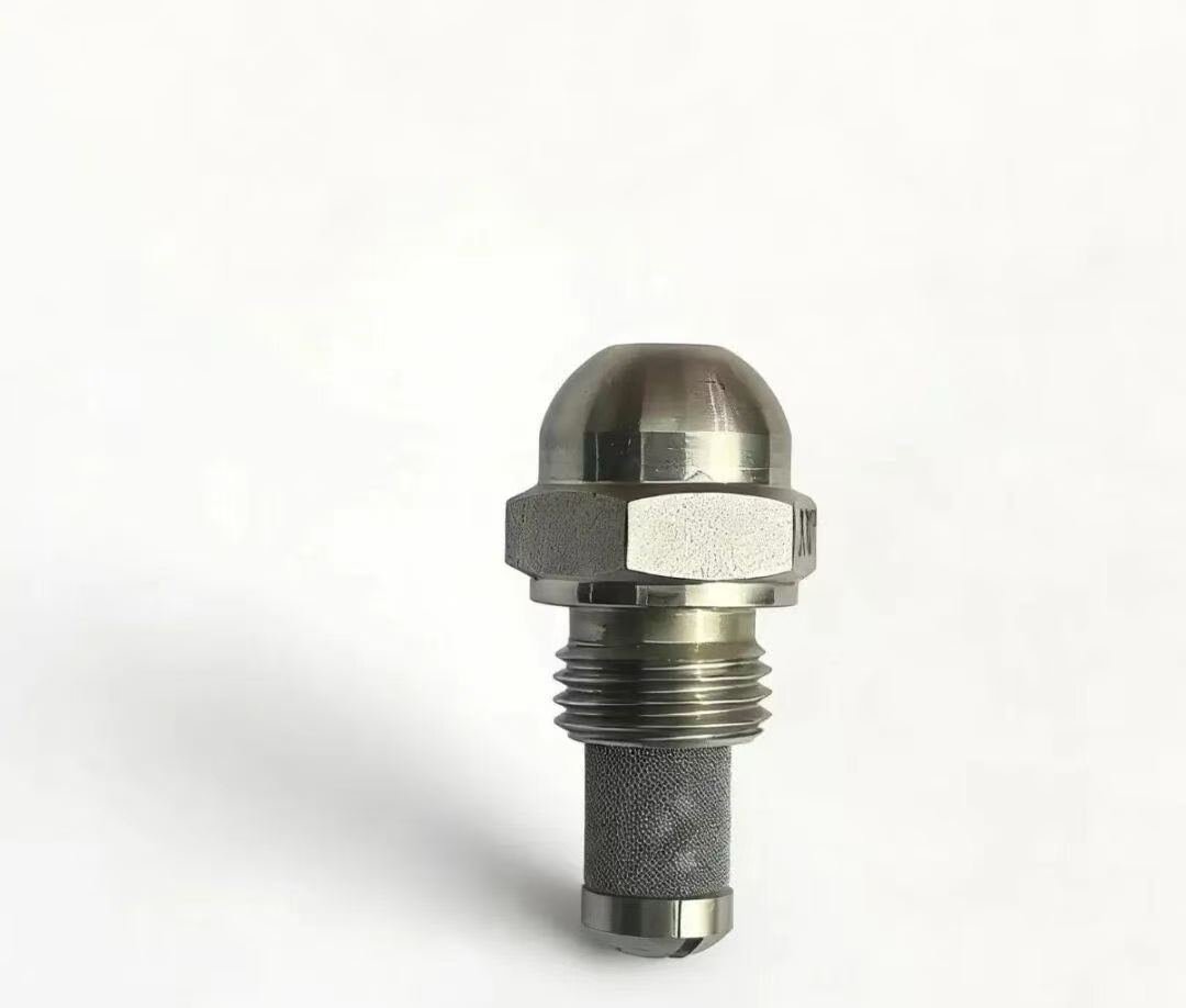
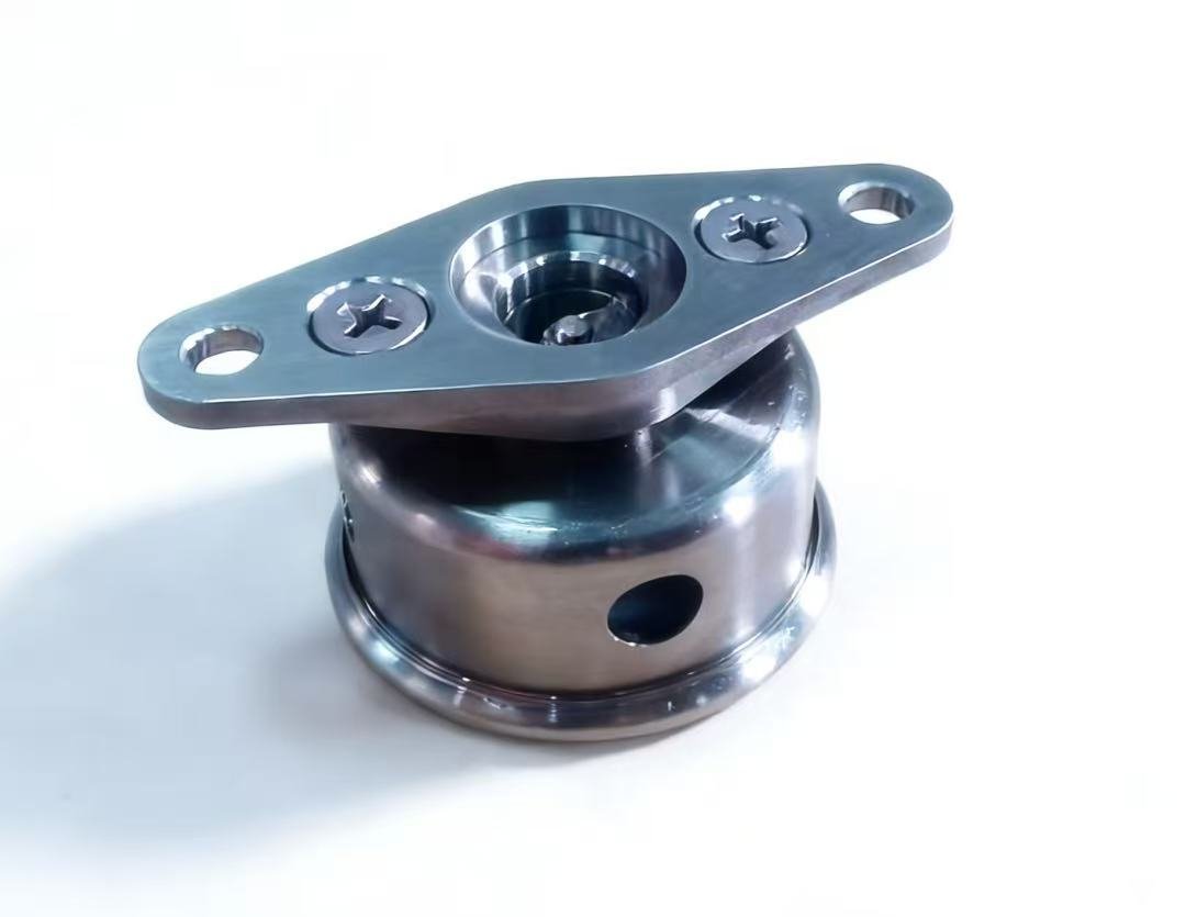
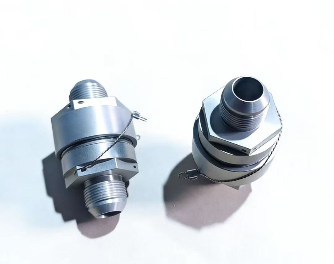
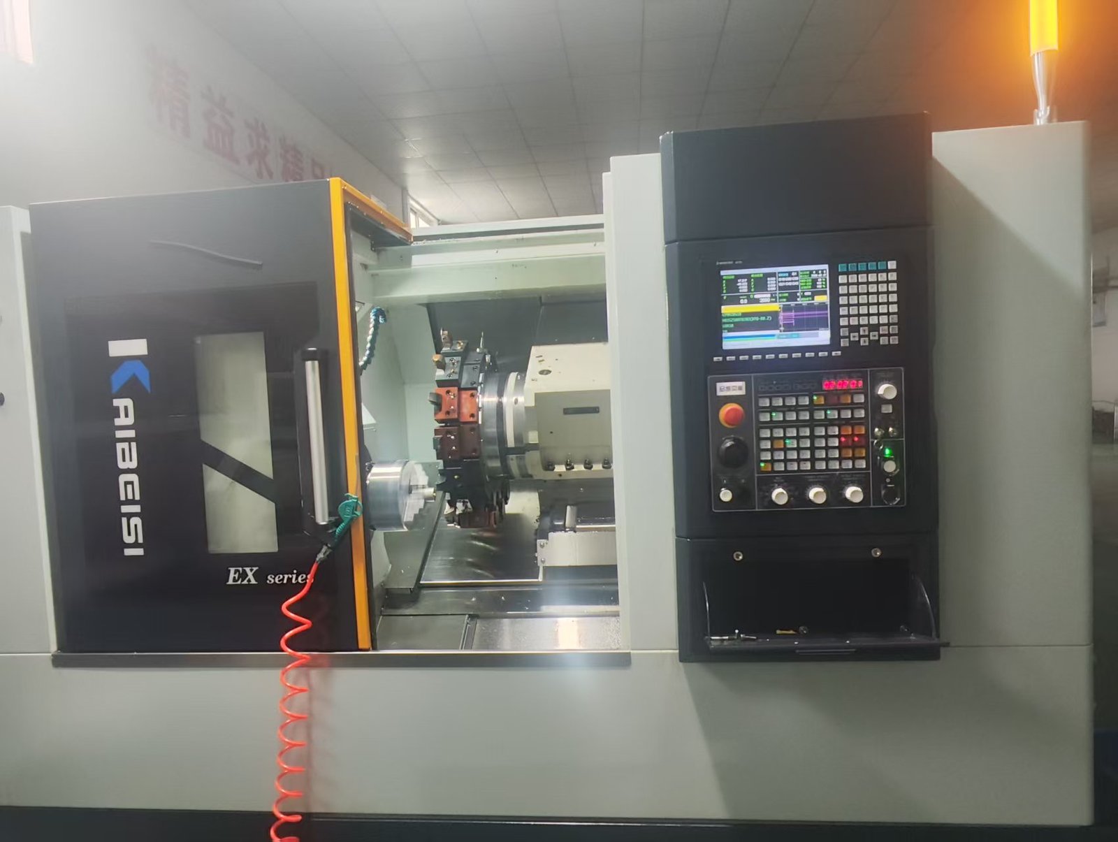
Process selection is a manufacturing decision made after reviewing the complete part, rather than a label a buyer has to get exactly right.
Identify the turned diameters, bores and features referenced to the centerline. A primarily rotational part usually starts with a turning review.
Mark flats, slots, cross-holes, pockets and multi-face patterns. Their location and access determine whether combined machining is practical.
Call out critical datums, fits and positional relationships between turned and milled features. These affect setup and inspection planning.
Provide prototype and repeat-order quantities. Setup effort, workholding and inspection scope may be evaluated differently across volumes.
Turn-milling does not automatically mean a lower price or shorter lead time. Tool access, setup, material, tolerances and batch size all matter.
Share a 3D model and controlled 2D drawing where available. Include material grade and condition, quantity, critical dimensions, threads, finish, inspection records, delivery destination and target date. LCFET can then review turning, milling or a combined route against the actual requirements.
Use these pages to see the types of components LCFET can review, then send the drawing for a part-specific assessment.
Shafts, sleeves, bushings, fittings and other rotational parts.
VIEW CNC TURNINGPlates, brackets, housings and parts with holes, slots or pockets.
VIEW CNC MILLINGParts combining turned profiles with off-axis or milled features.
VIEW TURN-MILLINGEngineering samples and small batches before repeat production.
VIEW PROTOTYPESTell us what the part must do. We will review its geometry, critical requirements and a practical machining route before quotation.